
The main technical parameters
No. | Item Name | Value | Unit |
1 | Grinding diameter | Φ120 | mm |
2 | Number of grinding heads | 3 | set |
3 | Grinding rod speed | 220 | r/min |
4 | Grinding speed | 9 | r/min |
5 | Feeding maximum particle size | -1.5 | mm |
6 | Product size | -1.074 | mm |
7 | Maximum throughput per | 30 | g | |||
grinding | ||||||
Model | AO27124 | |||||
8 | Electric | |||||
Power | 380 | w | ||||
motor | ||||||
Rotating speed | 1400 | r/min | ||||
9 | Dimensions (length, width, | 780*750*500 | mm | |||
height) | ||||||
10 | weight | 105 | Kg | |||
Machine usage and principle
XPM-Φ120X3 three-head grinding machine is a kind of grinding equipment for dry grinding and analysis of samples. It is mainly used for grinding and analyzing samples in the laboratory of metallurgy, building materials, chemical industry, coal, hydropower, commodity inspection, geology, etc. The aspect is used as a fine material in general.
Main structure description
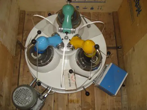
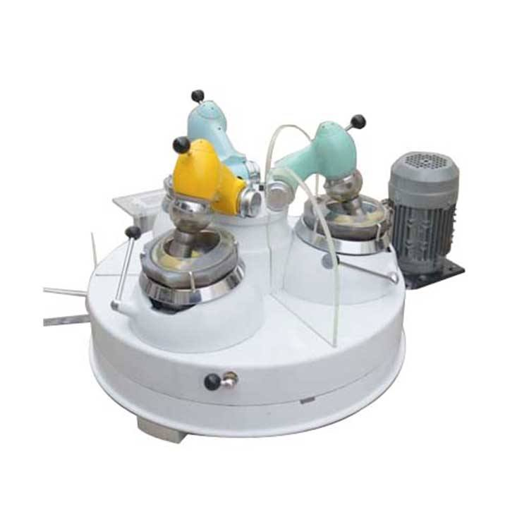
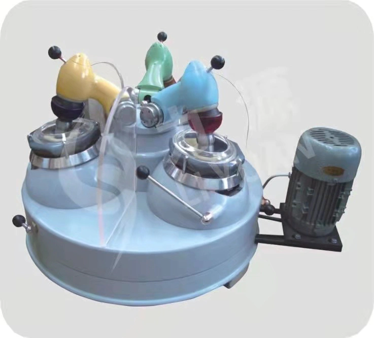
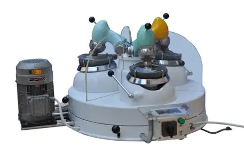
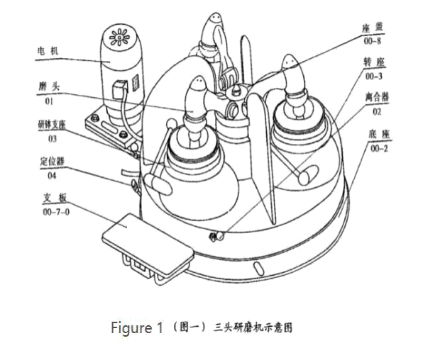
The structure of the machine is shown in Figure 1 - Figure 5. The overall structure is shown in Figure 1. It consists of three sets of grinding heads, clutches, mortar supports and positioners.
The grinding head (01), the mortar support (03) and the clutch (02) are evenly mounted on the rotary seat (003) at 120°, and the rotary seat is mounted in the bearing of the base (00-2) at the front of the base It is equipped with a receiving support plate (00-7- 0) and an electric appliance, and a motor is mounted on the left side. When the clutch is turned on, the motor rotates the grinding head through the pulley, the gear shaft (Fig. 2: 02-19), and the universal joint (Fig. 2: 02-2- 10- 0, Fig. 3: 01-21-0) . The other end of the gear shaft (02-1) meshes with the gear of the mortar holder (Fig.
4: 03-18). Due to the relative rotation of the grinding rod and the relative rotation of the mortar, the pressure grinding material is generated by the self-weight of the grinding head.
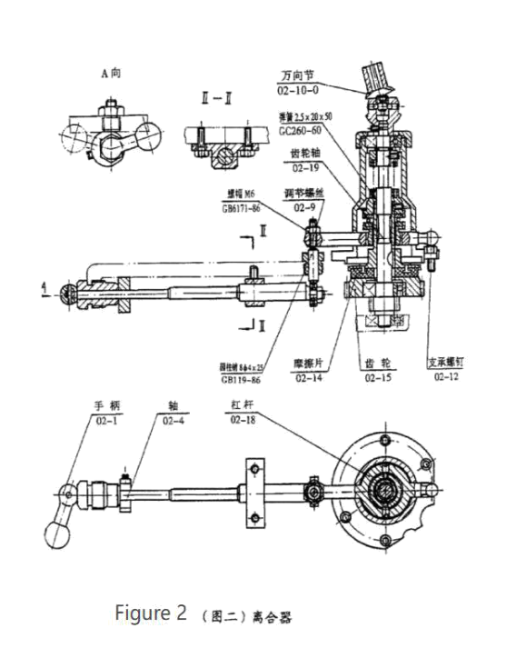
The clutch is shown in Figure 2 and is a normally closed dry friction clutch. The combination and disengagement of the friction clutch is achieved by the up and down swing of the lever (02-8) around the support pin (02-12). When the lever is lifted up, the spring is compressed, and the friction plate (02-14) and the gear (02 - 15) Disengage. When the lever is moved down, the spring is reset, and the friction plate is attached to the end face of the gear to transmit power.
The up and down movement of the lever is achieved by the joystick (02-1). When the handle is on the right side of the figure, the clutch fits and rotates counterclockwise to the left. The shaft (02-4) mounted on the turntable pushes the pin by eccentric action, and lifts the adjusting screw of the lever (02- 18) (02-9) ), the lever swings upwards to disengage the clutch. During use, when the friction lining wears, loosen the nut and adjust the adjusting screw (02-9) downwards.
Since each pair of laps has a separate clutch operation, the movement of the three pairs of laps does not affect each other, and it can work at the same time, and one or two pairs can be operated.
The structure of the grinding head is shown in Figure 3. When the power is transmitted from the clutch universal joint, the bevel gear shaft (01-16) and the bevel gear (01 -11) drive the shaft (01-12) to rotate. Due to the eccentric action, the shaft ( 01-12) Drive the bearing housing (01-2) and the grinding rod seat (01-7) on it, and the grinding rod (01-6) makes a selective rotary motion around the shaft (01-12).
The adjustment of the grinding head pressure is achieved by the tension of the adjusting spring (01-28).
Since two shafts (01-30) are mounted on both sides of the rotating arm, the two shafts are respectively mounted on the bearing of the bearing housing (01-29), and (01-29) is fixed on the seat cover (Fig. 1: 00-8) Up, so the rotating arm can rotate around the axis of the shaft (01- 30). In order to adjust the pressure of the grinding head, a coil spring (01-28) is mounted on the outer side of the left and right bearing housings (01-29). One end is stuck on the cover (01 -26) and the other end is on the shaft (01-30). When loosen the semi- circular head screw (GB67-85M3x5), if the cover (01 -26) is rotated away from the grinding center, the coil spring (01-28) will be tightened, and the pressure of the grinding head can be appropriately reduced. Otherwise, the grinding is performed. The pressure on the head can be increased as appropriate. The user can adjust the grinding object according to different grinding objects. When the factory is shipped, the coil spring (01-28) is adjusted to reduce the pressure of the grinding head.

We are not only provider but also end user. Rich experience to provide the most reasonable and high-quality solutions from the perspective of customers when providing services to customers.
Copyright © 2021 Y&X Beijing Technology Co., Ltd. | All Rights Reserved
We are here to help you! If you close the chatbox, you will automatically receive a response from us via email. Please be sure to leave your contact details so that we can better assist